


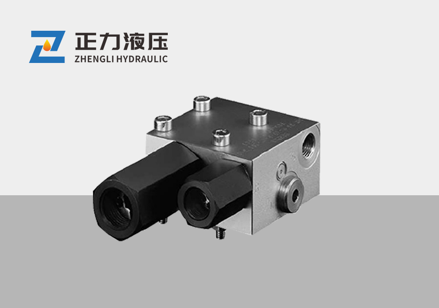
Balance valve ZLHDV 33P-11
Technical Data Sheet
Work pressure: Pmax=360... 450 bar
Flow rate: Qmax=80L/min
overview
summary:
According to the industrial standard ISO1219-1, these valves belong to the pressure range. They can prevent negative cuts that are pulled or pushed from accelerating uncontrollably in the negative cutting direction, or prevent the actuator from moving at a speed higher than the set (determined by the pump side oil supply). Therefore, these components can prevent the breakage or possible damage of the oil column. Balance width is mainly used for lifting and swinging using dual acting actuators (hydraulic cylinders, hydraulic motors).
Rotating or similar mechanisms. This control is achieved by throttling the return oil of the corresponding actuator. The balance valve generates a flow resistance that is always slightly higher than the load pressure. This back pressure is only generated under negative load conditions. However, if the load is positive, that is, the load acts in the opposite direction of motion, the balance width will be fully opened, allowing for smooth oil return. The throttle element is self-adjusting and can continuously adapt to any changes in load conditions. This is achieved through the balance of forces, where one side of the wide functional element acts on the incoming and outgoing forces (from the executing element of the action); There is a broad spring force acting on the other side. The ZLHDV type is specifically designed for use in situations where it has a strong tendency to swing due to its own elasticity. When this balance valve is used together with a load sensitive proportional multi way directional valve that has a two-way inlet regulating valve for each valve block, it will have more advantages. Of course, they should be installed on the corresponding pipelines between the actuator and the reversing width. As an independent component, ZLHDV type valves can effectively intervene in vibration circuits, just as this vibration circuit is caused by hydraulic cylinders with suspended loads, flow regulating valves with directional widths, or pressure/flow regulators of variable displacement pumps.
Its vibration reduction performance has stronger adaptability than general measurement methods (such as changing the characteristic curve of the flow control valve in the proportional directional valve), and its effect can be adjusted more accurately. The fluctuating load pressure affects the movement of the regulating element that continuously changes the throttling area. However, its response is slightly delayed, slowed down, and trained weakly by a specially designed combination of Yangni elements. This will effectively suppress vibrations caused by starting, stopping, or sudden transitions from full speed to crawling speed. Eventually, they will be suppressed during the formation stage and quickly disappear.

Selection code:

Example of ordering:
Example of ordering corresponding functional symbols
Unidirectional balancing valve for constant load direction
When the load drops, open the V → F direction passage from the other side (the inlet circuit of the actuator) through the S port.
Example of ordering structures that can be supplied:

External dimensions:

Appendix:
Adjustable throttling for damping:
The optimal damping characteristics can be obtained within the adjustment range. This task can be completed on-site. It is recommended to include this instruction and diagram in the equipment's operating manual or user manual. Before adjusting the throttle screw, the locking nut with a wrench opening of 10mm must be fully loosened (seal the locking nut), otherwise the vulcanized sealing ring will be damaged by the thread!
Throttle screw
(Headless screw ISC 4026M61h-8.8-A2K)
Attention: When externally rotating the throttle screw, the maximum should not exceed 17mm (as shown in the figure on the right)!
The adjustable range of throttling cannot be fixed inside the valve body due to structural limitations.

The opening pressure P on the oil inlet side:
The required pump pressure P causes the load to move against the balance valve located downstream (V → F direction). The pressure cannot be accurately predicted; It depends on the following parameters: the area ratio of the hydraulic cylinder piston cross-section A in: A out, the internal operating area ratio of the balance valve (opening ratio as described in Section 2), the load pressure at that time, and the flow resistance APF (R) of all downstream additional throttling units (such as the return line, directional valve A → R in this example) up to the oil tank
The set value of the additional buffer width installed in the oil inlet pipeline of the actuator must be adjusted high enough to withstand the highest opening pressure (no-load state) beyond the set value of the main relief valve. The recommended values for maximum set pressure of 370 bar or 250 bar and maximum flow rate (depending on the valve code in Section 2) are: P inlet max ≈ 130 ··: · 170 bar, when the set pressure is 370 bar
≈ 100 ··· 140 bar, when the set pressure is 250 bar
When the area ratio of the hydraulic cylinder piston cross-section A is about 2 ··· 0.5, depending on the opening ratio, the return oil flow resistance can increase these standard recommended values by approximately (1.1 ··· 3.5) xAPF (R). If necessary, the pressure limiting valve can be re adjusted on site.

Important note: The additional drain port of the bidirectional balancing valve (such as ZLHDV33-21L - ····) described on page 2 of page 3 can reduce the impact of flow resistance back to the fuel tank. Another advantage is that in emergency situations, the hand pump can be connected to the drain pipe.
Previous article:Balance valve ZLHDV 33P-15
Next article:Balance valve ZLHDV 33H-15
Customer Assistance
Product Series
News and information
NingboZhengliHydraulicTechnologyCoLtd


Copyrighto2022-2032
NingboZhengliHydraulicTechnologyCoLtd
All Rights Reserved